I won't say you can't do it... but it does sound a lot harder than using an Arduino.

One of the really nice things about using an Arduino to control the cams is that there is a ton of documentation on the internet about how to hook things up to it, and how to write software to handle incoming signals and generate outgoing signals. And in between the code that I wrote to say things like "call this function when this input pin changes state" or "set this output pin to x%" there's a layer of code written by people who understand the Arduino's CPU at a deeper level than I do.
And if you have to add a circuit to translate between signal types - for example to measure cam signal timing and generate an analog voltage to feed to the TGV inputs - then you're halfway to creating the hardware for a standalone controller.
Does the ECU have proportional control over the TGV motors? Or does it just switch them on and off for a short period to open and close the TGVs? I thought it was proportional but I heard it was really just on/off... I never really looked into it.
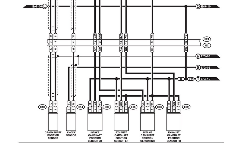
As I mentioned, cam position sensing is based on the timing between the crankshaft and signals from the camshaft position sensors... I was not confident enough in my electronical abilities to wire into the crank position sensor, so I painted a white mark on a cam pulley and placed an optical sensor above it... the photo below shows the signal from my optical sensor on top, and the two traces below it are the left and right cam sensors.
When the signal from the crank sensor begins, the Arduino starts two timers. When it sees the each signal from the cam sensors, it look at the elapsed time, and the RPM, and it computes the cam angle relative to the crankshaft. Each sensor is hooked up to an Arduino pin that can generate an interrupt when the signal changes. It measures the cam angles at rest (no power to the solenoids) and uses that to get a baseline, then it energizes the solenoids to retard the cams from that baseline.
To measure that timing accurately you'll want an input pin on the ECU that can be used to trigger an interrupt, or (better yet) one that is hooked up to a hardware timer (aka "capture"). You might be able to measure both cam angles with a single CPU input, since the pulses are 90 degrees apart.
The solenoids need to be controlled independently though, each with its own feedback loop that compares the current cam phase to the desired phase, and adjusts the PWM signal accordingly. The PWM signal is about 55% at neutral, and it increases to retard the cam, or decreases to advance it, then goes back to neutral when the cam is where it should be. (Control would be a lot simpler if the cam angle was proportional to the PWM duty cycle, but that's not how it works.)
I really doubt that you can use the TGV inputs to trigger interrupts... it's used for an analog signal, and timing doesn't matter for that signal... If you can find a datasheet for the CPU, it will list which pins can trigger interrupts and with that information and an opened ECU, and a wiring diagram, you might be able to figure out what those CPU pins are currently connected to. I say "might" because if the ECU circuit board has more than two layers of traces it will be hard to figure out which pins go where. But there's a good chance that 16-bit ECUs use 2-layer circuit boards - I think the odds are in your favor.
To control the solenoids, you need two outputs that can put out some kind of variable signal, either voltage or PWM (duty cycle). Again, you could look at the CPU's datasheet to see what CPU pins can do PWM (or analog out), and see what's currently connected to those CPU pins. Or you can look through a wiring diagram to see which ECU pins carry what sorts of signals. I'm not sure which will be easier, it might be necessary to try both.