|
RomRaider
Documentation
Community
Developers
|
| Author |
Message |
|
Bamofo
|
Post subject: Experimental Code Question for Front O2 sampling  Posted: Posted: Tue Aug 28, 2012 2:35 pm |
|
 |
| Experienced |
Joined: Mon Jul 02, 2007 11:46 am
Posts: 430
|
|
Hello Ive been talking to quite a few of you via PM about this specific request but i wanted to make a general open post about it in case anyone has stumbled across what im looking for.
On the 07 STI rom or any STI rom im looking for the frequency around how often the Front O2 sensor is polled for reading. If i could go pull this myself i would but im not there yet.
More specifically im looking for if there is a counter that is based off the clock that can be adjusted to poll less or more often on the front O2 or if it is just a routine called every time the CPU has time to get the routine.
Second, if it is the later of the two and it just calls the routine as frequent as possible, how hard would it be to add in a jmp command or a routine loop that counts to a specified value before actually polling the Front O2 sensor again? I know it wouldn't be directly linked to Seconds, Milliseconds or anything like that but the offset loop could be potentially what myself and others need with big turbo applications.
What im trying to get from this is the ability to control the idle better when you relocate the O2 Sensor behind the turbo. I know that certain JDM version of the STI had a twinscroll setup stock with the O2 sensor behind the turbo and it idles fine.... however when you try to put a twinscroll setup on any other version you basically need to ditch the Stock ECU and go with a hydra or AEM to make it right... With all the efforts you guys/gals have been putting in lately im almost to the point that i have a 6.8:1 compression car with a twinscroll 40R that idles and drives like stock... this is the final piece.
Currently what i have done is trick the ECU by scaling the max/min values the ecu see's from the voltage swing of the O2 sensor. Meaning it will never receive a value of 20afr or 9afr like to stock values permit.
_________________
--2008 3.6 Tribeca --
--2007 STI limited Panda--
--Twinscroll GT40R 2.35L--
|
|
| Top |
|
 |
|
dschultz
|
Post subject: Re: Experimental Code Question for Front O2 sampling Posted: Tue Aug 28, 2012 10:16 pm |
|
|
| RomRaider Developer |
Joined: Thu May 21, 2009 1:49 am
Posts: 7323
Location: Canada eh!
|
|
The ADC routine I'm sure is on a timer, BUT it polls all the ADC ports in the same routine, so changing the timer will change every analog input polling cycle.
You'd need to write and inject custom code to change the routines behaviour. You can base it on microseconds if that is the desire.
|
|
| Top |
|
|
|
Bamofo
|
Post subject: Re: Experimental Code Question for Front O2 sampling Posted: Wed Aug 29, 2012 1:33 am |
|
|
| Experienced |
Joined: Mon Jul 02, 2007 11:46 am
Posts: 430
|
|
Cool. Im working on getting to the routines tonight and tomorrow. Hopefully between myself and the engineers at my work i can get some code that makes sense formed. Adding in the jump and count routine shouldnt be too bad its just figuring out all the code first.... If i find anything useful i will post it but im sure i will have a bunch of questions before i even remotely find what im looking for.
_________________
--2008 3.6 Tribeca --
--2007 STI limited Panda--
--Twinscroll GT40R 2.35L--
|
|
| Top |
|
|
|
Merp
|
Post subject: Re: Experimental Code Question for Front O2 sampling Posted: Wed Aug 29, 2012 2:30 am |
|
|
| Experienced |
 |
Joined: Thu Jul 23, 2009 5:46 pm
Posts: 863
|
|
In your A2UJ000J, it appears that the main ADC routine is at 0x6E68. The base address for the ADC Table (direct voltages to sensors after polling) is located at 0xFFFF5BFC. I don't have the base defined as a voltage, but it represents some sensor voltage. The following three are battery volts, map volts, then maf volts.
Changing the polling rate for a single ADC is going to be relatively involved, I would exhaust all options with the smoothing function first, as nearly the same end result could be achieved with a properly configured smoothing function.
In A2UJ000J, the smoothing function used for the Front O2 is found at 0x23FC. The jsr from the Front O2 routine is at 0xBE58, where the smoothing constant is loaded to fr6 from r1. The smoothed value is immediately thereafter used as a lookup for the O2 sensor scaling table. If you trace the r1 ram address, you'll find the table I had defined ( 3D Engine load x Smoothed MAF ) for the smoothing factor.
_________________
Please do not send me support questions via PM, use the forum instead!
|
|
| Top |
|
|
|
dschultz
|
Post subject: Re: Experimental Code Question for Front O2 sampling Posted: Wed Aug 29, 2012 2:46 am |
|
|
| RomRaider Developer |
Joined: Thu May 21, 2009 1:49 am
Posts: 7323
Location: Canada eh!
|
|
I guess I should have mentioned that after the ADCs are read to RAM, the various raw values are converted to the real values they represent. I suspect these routines are also on a timer and may be the same or a different one. Once the values are converted they are also checked for limits, usually to trigger CELs.
|
|
| Top |
|
|
|
Bamofo
|
Post subject: Re: Experimental Code Question for Front O2 sampling Posted: Wed Aug 29, 2012 3:43 am |
|
|
| Experienced |
Joined: Mon Jul 02, 2007 11:46 am
Posts: 430
|
I think the hardest part of all this is trying to keep all the experimental definition files you make for me aside so when i copy a new set of definitions i dont lose all the hard work you did before  ill go find it and look again since i have an idea of what i was seeing for MAF values at idle today. Merp wrote: In your A2UJ000J, it appears that the main ADC routine is at 0x6E68. The base address for the ADC Table (direct voltages to sensors after polling) is located at 0xFFFF5BFC. I don't have the base defined as a voltage, but it represents some sensor voltage. The following three are battery volts, map volts, then maf volts.
Changing the polling rate for a single ADC is going to be relatively involved, I would exhaust all options with the smoothing function first, as nearly the same end result could be achieved with a properly configured smoothing function.
In A2UJ000J, the smoothing function used for the Front O2 is found at 0x23FC. The jsr from the Front O2 routine is at 0xBE58, where the smoothing constant is loaded to fr6 from r1. The smoothed value is immediately thereafter used as a lookup for the O2 sensor scaling table. If you trace the r1 ram address, you'll find the table I had defined ( 3D Engine load x Smoothed MAF ) for the smoothing factor. So the Load Scale is 0.60 to 1.20 and Smoothed MAF g/s is 20-44 Im assuming you want me to go change those scaling to be more specific for idle instead of for cruise? I can definetly give it a try in the morning... If I am seeing a huge swing in AFR i should be doing significantly more smoothing but this table seems way off from the ranges im looking for. So suggested scaling from my logging will change the Smoothed MAF from 2.5 - 50 and the load values of .50 - 1.25 Ill give it a shot tomorrow with all the o2 sensor values back to stock and see what i can pull out of my butt for results.
_________________
--2008 3.6 Tribeca --
--2007 STI limited Panda--
--Twinscroll GT40R 2.35L--
|
|
| Top |
|
|
|
Merp
|
Post subject: Re: Experimental Code Question for Front O2 sampling Posted: Wed Aug 29, 2012 5:01 am |
|
|
| Experienced |
|
Joined: Thu Jul 23, 2009 5:46 pm
Posts: 863
|
Bamofo wrote: I think the hardest part of all this is trying to keep all the experimental definition files you make for me aside so when i copy a new set of definitions i dont lose all the hard work you did before ill go find it and look again since i have an idea of what i was seeing for MAF values at idle today. This is where Git comes in handy  https://github.com/Merp/SubaruDefs/blob ... UJ000J.xml https://github.com/Merp/SubaruDefs/blob ... UJ000J.xml Bamofo wrote: Merp wrote: In your A2UJ000J, it appears that the main ADC routine is at 0x6E68. The base address for the ADC Table (direct voltages to sensors after polling) is located at 0xFFFF5BFC. I don't have the base defined as a voltage, but it represents some sensor voltage. The following three are battery volts, map volts, then maf volts.
Changing the polling rate for a single ADC is going to be relatively involved, I would exhaust all options with the smoothing function first, as nearly the same end result could be achieved with a properly configured smoothing function.
In A2UJ000J, the smoothing function used for the Front O2 is found at 0x23FC. The jsr from the Front O2 routine is at 0xBE58, where the smoothing constant is loaded to fr6 from r1. The smoothed value is immediately thereafter used as a lookup for the O2 sensor scaling table. If you trace the r1 ram address, you'll find the table I had defined ( 3D Engine load x Smoothed MAF ) for the smoothing factor. So the Load Scale is 0.60 to 1.20 and Smoothed MAF g/s is 20-44 Im assuming you want me to go change those scaling to be more specific for idle instead of for cruise? I can definetly give it a try in the morning... If I am seeing a huge swing in AFR i should be doing significantly more smoothing but this table seems way off from the ranges im looking for. So suggested scaling from my logging will change the Smoothed MAF from 2.5 - 50 and the load values of .50 - 1.25 Ill give it a shot tomorrow with all the o2 sensor values back to stock and see what i can pull out of my butt for results. It's an interesting table, because the axes are so closely related. Because the main difference between MAF and engine load is RPM, for a given MAF value on the X axis, the Y axis is a representation of RPM. For example, in the first column. 0.6g/rev at 20g/s represents 2000rpm. 1.2g/rev at 20g/s represents 1000rpm. As you go higher on the MAF, the rpm increases. (44g/s column is 4400 to 2200rpm from 0.6g/rev to 1.2g/rev). However, this breaks down MAF and engine load go out of range and the idle end up in the top left instead of bottom left. I would test by changing the top left cells around. Maybe try the 10 value at 1, 10, 25, 50, 95 and see if there is a noticeable improvement.. If that doesn't help, then try rescaling the axes such that idle range follows the same scheme as the the table (low rpm = higher smoothing). I'm also very curious to see the smoothing factor in action. Will try to get you a logger xml to watch it. On a more general note: I don't think chasing the sensor is the best way to solve this problem. The two issues with relocation are: 1. Changes in pressure cause changes in AFR reading 2. Latency has been increased I don't think 1 is a big factor. As for two, it is simply impossible to reduce the latency unless you can predict afr. I would expect this change in latency to change control characteristics of any system that uses the afr signal. Especially so for those that use derivative and proportional corrections. So, I think the best solution is changes to the feedback control system for CL fueling.
_________________
Please do not send me support questions via PM, use the forum instead!
|
|
| Top |
|
|
|
Bamofo
|
Post subject: Re: Experimental Code Question for Front O2 sampling Posted: Wed Aug 29, 2012 12:34 pm |
|
|
| Experienced |
Joined: Mon Jul 02, 2007 11:46 am
Posts: 430
|
Why cant you guys live closer... this is the best conversation ive had in weeks  Finally other people that understand the words coming out of their mouths. I will take into consideration what you wrote below during my testing. Merp wrote: Bamofo wrote: I think the hardest part of all this is trying to keep all the experimental definition files you make for me aside so when i copy a new set of definitions i dont lose all the hard work you did before ill go find it and look again since i have an idea of what i was seeing for MAF values at idle today. This is where Git comes in handy https://github.com/Merp/SubaruDefs/blob ... UJ000J.xml Bamofo wrote: Merp wrote: In your A2UJ000J, it appears that the main ADC routine is at 0x6E68. The base address for the ADC Table (direct voltages to sensors after polling) is located at 0xFFFF5BFC. I don't have the base defined as a voltage, but it represents some sensor voltage. The following three are battery volts, map volts, then maf volts.
Changing the polling rate for a single ADC is going to be relatively involved, I would exhaust all options with the smoothing function first, as nearly the same end result could be achieved with a properly configured smoothing function.
In A2UJ000J, the smoothing function used for the Front O2 is found at 0x23FC. The jsr from the Front O2 routine is at 0xBE58, where the smoothing constant is loaded to fr6 from r1. The smoothed value is immediately thereafter used as a lookup for the O2 sensor scaling table. If you trace the r1 ram address, you'll find the table I had defined ( 3D Engine load x Smoothed MAF ) for the smoothing factor. So the Load Scale is 0.60 to 1.20 and Smoothed MAF g/s is 20-44 Im assuming you want me to go change those scaling to be more specific for idle instead of for cruise? I can definetly give it a try in the morning... If I am seeing a huge swing in AFR i should be doing significantly more smoothing but this table seems way off from the ranges im looking for. So suggested scaling from my logging will change the Smoothed MAF from 2.5 - 50 and the load values of .50 - 1.25 Ill give it a shot tomorrow with all the o2 sensor values back to stock and see what i can pull out of my butt for results. It's an interesting table, because the axes are so closely related. Because the main difference between MAF and engine load is RPM, for a given MAF value on the X axis, the Y axis is a representation of RPM. For example, in the first column. 0.6g/rev at 20g/s represents 2000rpm. 1.2g/rev at 20g/s represents 1000rpm. As you go higher on the MAF, the rpm increases. (44g/s column is 4400 to 2200rpm from 0.6g/rev to 1.2g/rev). However, this breaks down MAF and engine load go out of range and the idle end up in the top left instead of bottom left. I would test by changing the top left cells around. Maybe try the 10 value at 1, 10, 25, 50, 95 and see if there is a noticeable improvement.. If that doesn't help, then try rescaling the axes such that idle range follows the same scheme as the the table (low rpm = higher smoothing). I'm also very curious to see the smoothing factor in action. Will try to get you a logger xml to watch it. On a more general note: I don't think chasing the sensor is the best way to solve this problem. The two issues with relocation are: 1. Changes in pressure cause changes in AFR reading 2. Latency has been increased I don't think 1 is a big factor. As for two, it is simply impossible to reduce the latency unless you can predict afr. I would expect this change in latency to change control characteristics of any system that uses the afr signal. Especially so for those that use derivative and proportional corrections. So, I think the best solution is changes to the feedback control system for CL fueling.
_________________
--2008 3.6 Tribeca --
--2007 STI limited Panda--
--Twinscroll GT40R 2.35L--
|
|
| Top |
|
|
|
dschultz
|
Post subject: Re: Experimental Code Question for Front O2 sampling Posted: Wed Aug 29, 2012 12:46 pm |
|
|
| RomRaider Developer |
Joined: Thu May 21, 2009 1:49 am
Posts: 7323
Location: Canada eh!
|
Merp wrote: Bamofo wrote: I think the hardest part of all this is trying to keep all the experimental definition files you make for me aside so when i copy a new set of definitions i dont lose all the hard work you did before ill go find it and look again since i have an idea of what i was seeing for MAF values at idle today. This is where Git comes in handy https://github.com/Merp/SubaruDefs/blob ... UJ000J.xml And how do you relate that def in Git back to this post where the commentary is about why it was created in the first place? I suggest you standardize on a method for this so people know what they are looking when they browse the repo. Even you are going to forget why you made the def over time without so documentation for it.
|
|
| Top |
|
|
|
Merp
|
Post subject: Re: Experimental Code Question for Front O2 sampling Posted: Wed Aug 29, 2012 2:16 pm |
|
|
| Experienced |
|
Joined: Thu Jul 23, 2009 5:46 pm
Posts: 863
|
dschultz wrote: Merp wrote: Bamofo wrote: I think the hardest part of all this is trying to keep all the experimental definition files you make for me aside so when i copy a new set of definitions i dont lose all the hard work you did before ill go find it and look again since i have an idea of what i was seeing for MAF values at idle today. This is where Git comes in handy https://github.com/Merp/SubaruDefs/blob ... UJ000J.xml And how do you relate that def in Git back to this post where the commentary is about why it was created in the first place? I suggest you standardize on a method for this so people know what they are looking when they browse the repo. Even you are going to forget why you made the def over time without so documentation for it Table name/description is enough information for me, but I can throw a link in the templates.
_________________
Please do not send me support questions via PM, use the forum instead!
|
|
| Top |
|
|
|
td-d
|
Post subject: Re: Experimental Code Question for Front O2 sampling Posted: Wed Aug 29, 2012 3:17 pm |
|
|
| Moderator |
Joined: Thu May 20, 2010 8:01 am
Posts: 3117
Location: Johannesburg, South Africa
|
|
Interesting find, Merp - I'm finding this table consistently in similar locations in other roms.
Keen to see what impact this has, and where it can be used.
_________________
He who dies with the most gadgets wins.
Please do not PM me - use the email option.
|
|
| Top |
|
|
|
Bamofo
|
Post subject: Re: Experimental Code Question for Front O2 sampling Posted: Wed Sep 05, 2012 1:49 pm |
|
|
| Experienced |
Joined: Mon Jul 02, 2007 11:46 am
Posts: 430
|
I've been working quite hard to get the oscillation from the Front O2 Correction under control with no luck. I have the MAF smoothing turned up to 98%. Note that over or equal to 100 and the front O2 sensor sits on 11.15 or w/e your min value you have setup for it to read is.... With that being said it still oscillates and without either a delay, less polling frequency, Less overall correction from the Front A/F, or Reducing the overall scaling of the Front O2 table so it doesn't think its changing as much as it is i am up the creek without a paddle. The overrun tables that are referenced in another thread are unbelievable though. I added in the Delta of my idle compared to stock and it almost doesn't stall at all. Pulses but doesn't stall. With a little more tweaking i will be half way to having a stock driving car with a rotated 40R Any feedback or suggestions of what i should do next would be great. On the other hand the MAF smoothing did help a TON... but still not enough for my application. I can see this being used a lot with draw through on a big turbo or blow thru with a big turbo... just not enough for relocating the O2 behind the turbo...
_________________
--2008 3.6 Tribeca --
--2007 STI limited Panda--
--Twinscroll GT40R 2.35L--
|
|
| Top |
|
|
|
Merp
|
Post subject: Re: Experimental Code Question for Front O2 sampling Posted: Wed Sep 05, 2012 6:11 pm |
|
|
| Experienced |
|
Joined: Thu Jul 23, 2009 5:46 pm
Posts: 863
|
|
Do you mean maf/engine load smoothing that I use for SD, or the AF smoothing table?
For anyone interested in analysis for this, I'm working on the AF #1 correction limits and PID
Rom: A2UJ000J
Have a look at the routine at 0x2A59C. It is passed two base addresses for RAM parameters on r4 and r5, and then uses base offset addressing to load/store them.
Around 0x2A298 is where these lookup tables and subroutines are loaded/executed.
There are a few subroutines used:
0x2430 - zero safe division
0x2488 - low pass filter
0x2498 - band pass filter
The last use of the band pass filter looks like a hard coded af correction limit.
Just before that, there is a soft coded limit that uses RAM values for the limits.
I've found RAM parameters that store the current derivative gain and proportional gain, as well as two arrays that represent integral gain (previous correction array, and what I assume is a 'weighting' factor).
Prop gain is a bit convoluted, but I have found a 2d table and some constants that may be useful in adjusting it. I have yet to find the calculation for derivative gain, it may be indirectly addressed.
_________________
Please do not send me support questions via PM, use the forum instead!
|
|
| Top |
|
|
|
nsfw
|
Post subject: Re: Experimental Code Question for Front O2 sampling Posted: Wed Sep 12, 2012 7:24 am |
|
|
| Moderator |
Joined: Thu Nov 23, 2006 2:23 am
Posts: 2565
|
Bamofo wrote: I've been working quite hard to get the oscillation from the Front O2 Correction under control with no luck. [...]
With that being said it still oscillates and without either a delay, less polling frequency, Less overall correction from the Front A/F, or Reducing the overall scaling of the Front O2 table so it doesn't think its changing as much as it is i am up the creek without a paddle.
[...]
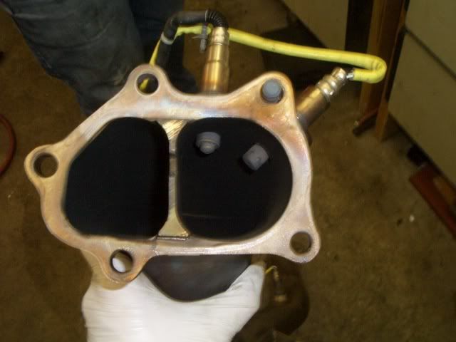
On the other hand the MAF smoothing did help a TON... but still not enough for my application. I can see this being used a lot with draw through on a big turbo or blow thru with a big turbo... just not enough for relocating the O2 behind the turbo... I relocated my front O2 sensor to my downpipe about 3 years ago and I haven't noticed any side-effects at all... http://i193.photobucket.com/albums/z151 ... lmouth.jpgIf the oscillation you're talking about is something that you mostly only see during cruise, it's an emissions trick that the ECU does deliberately. The catalytic converter has two different chemical processes, and the rich/lean oscillation toggles between them. I haven't verified this myself yet but I think the oscillation should go away if AF Correction #3's limits are set to zero. Can anyone confirm that? I haven't dug up the AFC#3 tables in my own ROM yet. There's a thread about the AFC#3 limits here: viewtopic.php?f=34&t=8131
_________________
2005 Legacy GT w/ ATP 3076, IWG, MBC, BCS, BC 272, LC, FFS, OMG
Please don't send questions via PM. Post a thread and send me a link to it instead. Thanks!
|
|
| Top |
|
|
|
Bamofo
|
Post subject: Re: Experimental Code Question for Front O2 sampling Posted: Wed Sep 12, 2012 4:33 pm |
|
|
| Experienced |
Joined: Mon Jul 02, 2007 11:46 am
Posts: 430
|
|
I can confirm that 0 in the AF3 Correction does not help. I did that last week with no benefit.
Merp is looking into the Front AF Correction but i have been looking into running in openloop all the time to see if that helps....
_________________
--2008 3.6 Tribeca --
--2007 STI limited Panda--
--Twinscroll GT40R 2.35L--
|
|
| Top |
|
|
Who is online |
Users browsing this forum: No registered users and 5 guests |
|
You cannot post new topics in this forum
You cannot reply to topics in this forum
You cannot edit your posts in this forum
You cannot delete your posts in this forum
You cannot post attachments in this forum
|
|


