RomRaider Logo

RomRaider

Open Source ECU Tools
 FAQ •  Register •  Login 

RomRaider

Documentation

Community

Developers

It is currently Thu Dec 25, 2025 1:31 am

All times are UTC - 5 hours [ DST ]


Post new topic Reply to topic  [ 14 posts ] 
Author Message
 Post subject: Editing voltage refrence points for IAT
PostPosted: Thu Apr 11, 2013 7:12 am 
Offline
Newbie

Joined: Tue Sep 04, 2012 2:37 am
Posts: 22
[EDIT]

I'm an idiot...lol I read the formula for the chart completely wrong in the spread sheet, disregard, I should only attempt to read things when I'm not falling asleep :D

[/edit]


I realize that CarBerry is a 1 man operation, and does not have the same size of staff of Cobb...

Using the GM IAT seems to be a very popular choice, however, the issue I have is because of the current limitations of open source 16-bit roms, it is not possible to edit the voltage reference points that the ECU uses to determine temperature, this unfortunately makes the use of the GM IAT inaccurate in some areas.

Now the people at Cobb have figured out how to edit the voltage reference points for 16-bit ecus, so I figure it should be possible for open source guys as well :)

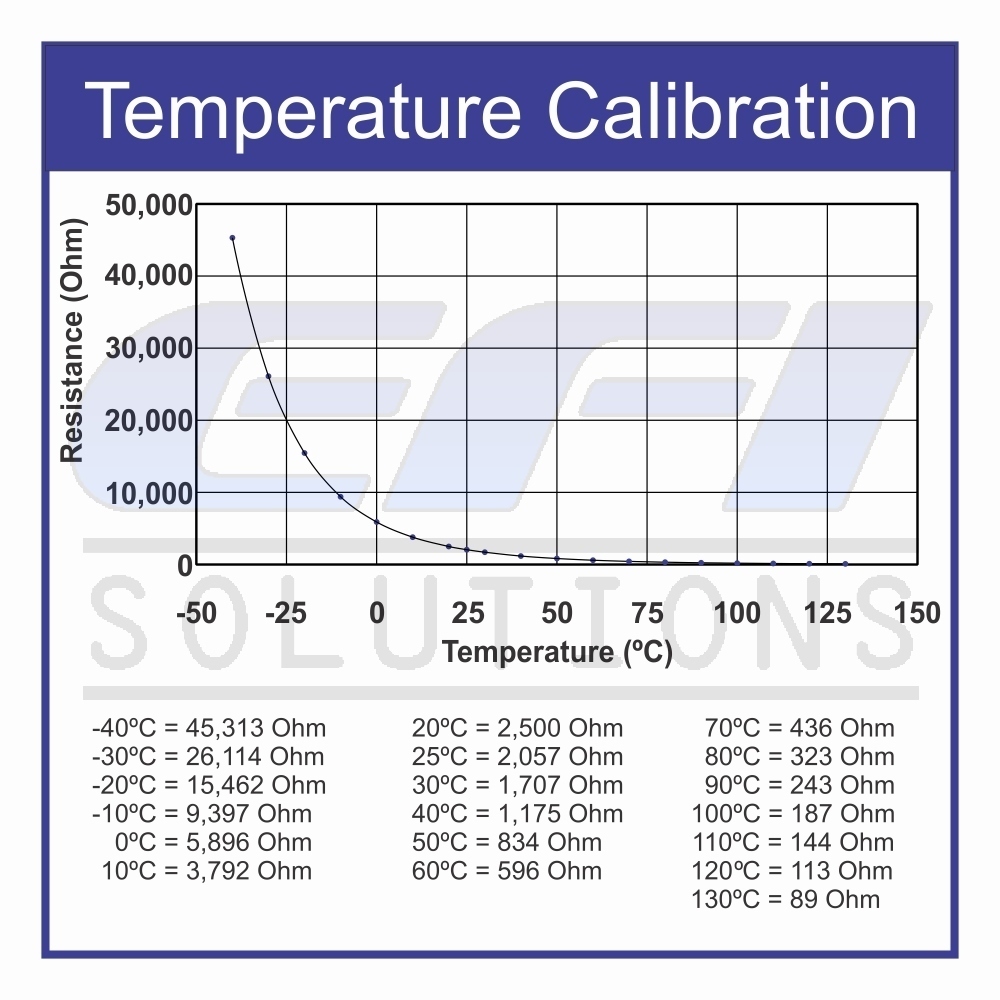
Credit for this graph goes to ryanr, who came out with the amazing spreadsheet found here: viewtopic.php?f=32&t=7797&start=30

Looking at the chart here:

Attachment:
File comment: IATscaling
IATscaling.jpg
IATscaling.jpg [ 67.56 KiB | Viewed 4338 times ]


We can see that because of the way the 16-bit OS roms require the fixed voltage that is pre-determined in the ECU, the way the curves go are different, and the accuracy becomes quite poor below 100F (37.78C) and above 140-160F (60C to 71C) Now I don't think there is much of an issue for the above the 140-160F accuracy, as if your car has IAT that high, it's time to consider better intercooling solutions :)

However, below that could be a problem for cold starts or those who have severe winters (at worse it only gets down to 0C where I live...but I've lived in -40C (also -40F) climates)

Now I can't see this being too catastrophic for people, but I would imagine it would cause the car to run quite rich, at these lower temps, or even running boost at lower temps with very efficient IC systems, which isn't a bad thing and is much better than running too lean, but it would reduce power at these lower temps, and it isn't optimal.

Of course I could just be over thinking this issue, and there may be no real issue, and that even with the odd scaling, the GM IAT could still be more accurate than the stock IAT (in blow through config) due to other variable factors.


Last edited by ozbugeyesti on Fri Apr 12, 2013 10:01 am, edited 1 time in total.

Top
 Profile  
 
 Post subject: Re: Editing voltage refrence points for IAT
PostPosted: Thu Apr 11, 2013 10:21 am 
Offline
Senior Member

Joined: Fri Feb 10, 2006 7:04 pm
Posts: 2661
Location: RIP
ozbugeyesti wrote:
We can see that because of the way the 16-bit OS roms require the fixed voltage that is pre-determined in the ECU, the way the curves go are different, and the accuracy becomes quite poor below 100F (37.78C) and above 140-160F (60C to 71C)

Dude, those curves are different because the temp sensors used are different! LOL.

_________________
MS41 Project Leader & Co-Developer (2012 - 2023)
MS41.3 https://sites.google.com/site/openms41/custom-code---ms41-3
MS41 ECU Portal https://sites.google.com/site/openms41/ms41-ecu-portal


Top
 Profile  
 
 Post subject: Re: Editing voltage refrence points for IAT
PostPosted: Thu Apr 11, 2013 11:06 am 
Offline
Experienced

Joined: Thu May 12, 2011 8:36 pm
Posts: 116
The GM = GM sensor with calculated scaling from supplied resistances
Cobb = GM/AEM sensor with their modified scaling
Carberry = JDM Spec C sensor (most likely)

_________________
MHI 16g powered 2000 WRX swapped RS


Top
 Profile  
 
 Post subject: Re: Editing voltage refrence points for IAT
PostPosted: Thu Apr 11, 2013 6:10 pm 
Offline
Newbie

Joined: Tue Feb 09, 2010 8:23 am
Posts: 99
Location: Tbilisi, Georgia
I have Bosch combo IAT+MAP sensor installed in manifold custom hole.
http://www.bosch.com.au/content/languag ... cation.pdf
How can I calibrate IAT Sensor?
2.5 K ohm / 68 degree is only data in Bosch data sheet.


Top
 Profile  
 
 Post subject: Re: Editing voltage refrence points for IAT
PostPosted: Thu Apr 11, 2013 7:27 pm 
Offline
Experienced

Joined: Thu May 12, 2011 8:36 pm
Posts: 116
maxouni wrote:
I have Bosch combo IAT+MAP sensor installed in manifold custom hole.
http://www.bosch.com.au/content/languag ... cation.pdf
How can I calibrate IAT Sensor?
2.5 K ohm / 68 degree is only data in Bosch data sheet.


Just did a bit of looking around for you and tried to adapt my spreadsheet to the Bosch TMAP like you have and the resistances that I could find are VERY high. This puts the entire scale of the sensor off (ex. at 4.74v it would be at 175deg F) This is the only scaling that I could find and I found it in 3-4 places but this very well may be for the LS application.

http://www.edelbrock.com/automotive_new ... tmap.shtml

_________________
MHI 16g powered 2000 WRX swapped RS


Top
 Profile  
 
 Post subject: Re: Editing voltage refrence points for IAT
PostPosted: Thu Apr 11, 2013 7:31 pm 
Offline
RomRaider Donator

Joined: Thu Jan 29, 2009 11:16 am
Posts: 523
maxouni wrote:
I have Bosch combo IAT+MAP sensor installed in manifold custom hole.
http://www.bosch.com.au/content/languag ... cation.pdf
How can I calibrate IAT Sensor?
2.5 K ohm / 68 degree is only data in Bosch data sheet.


Are you able to read the temperature off of that? It looked to me that the temperature was for pressure compensation vs. temperature?

_________________
Mods: http://www.romraider.com/forum/viewtopic.php?f=7&t=6789&start=5


Top
 Profile  
 
 Post subject: Re: Editing voltage refrence points for IAT
PostPosted: Fri Apr 12, 2013 9:59 am 
Offline
Newbie

Joined: Tue Sep 04, 2012 2:37 am
Posts: 22
ryanr wrote:
The GM = GM sensor with calculated scaling from supplied resistances
Cobb = GM/AEM sensor with their modified scaling
Carberry = JDM Spec C sensor (most likely)


Crap, nm, I read the excel formula wrong...wow...no more late nights for me after studying trying to decipher excel spread sheets lol...


Top
 Profile  
 
 Post subject: Re: Editing voltage refrence points for IAT
PostPosted: Fri Apr 12, 2013 12:58 pm 
Offline
Senior Member

Joined: Fri Feb 10, 2006 7:04 pm
Posts: 2661
Location: RIP
ryanr wrote:
maxouni wrote:
I have Bosch combo IAT+MAP sensor installed in manifold custom hole.
http://www.bosch.com.au/content/languag ... cation.pdf
How can I calibrate IAT Sensor?
2.5 K ohm / 68 degree is only data in Bosch data sheet.


Just did a bit of looking around for you and tried to adapt my spreadsheet to the Bosch TMAP like you have and the resistances that I could find are VERY high. This puts the entire scale of the sensor off (ex. at 4.74v it would be at 175deg F) This is the only scaling that I could find and I found it in 3-4 places but this very well may be for the LS application.

http://www.edelbrock.com/automotive_new ... tmap.shtml

Yeah, the sensor is too sensitive below 150F even after adding a 10Kohm resistor in parallel. What we really need to do is find a way to change the pullup resistor in the ECU to something in the 10K range. Then this will work perfectly.


Attachments:
Bosch TMAP IAT scaling.xlsx [14.98 KiB]
Downloaded 265 times

_________________
MS41 Project Leader & Co-Developer (2012 - 2023)
MS41.3 https://sites.google.com/site/openms41/custom-code---ms41-3
MS41 ECU Portal https://sites.google.com/site/openms41/ms41-ecu-portal
Top
 Profile  
 
 Post subject: Re: Editing voltage refrence points for IAT
PostPosted: Sun Apr 14, 2013 3:07 pm 
Offline
Newbie

Joined: Tue Feb 09, 2010 8:23 am
Posts: 99
Location: Tbilisi, Georgia
Thank you for scaling spreadsheet.
I hope my SD compensation table will be returned on previous scaling. It has been totally rescaled after installing this TMAP.


Top
 Profile  
 
 Post subject: Re: Editing voltage refrence points for IAT
PostPosted: Fri May 17, 2013 4:45 pm 
Offline
Experienced

Joined: Tue Dec 26, 2006 8:24 pm
Posts: 168
Location: ohio
So has anyone actually got this working? I used a gmiat sensor at one point post intercooler and it read off but i didn't have anything else.

_________________
2018 Kia Stinger GT2 AWD
JB4 / Tork tune / Intake / Muffler HP?

1997 Impreza Wagon.
E85 EJ257 408/420 18g

2003 Impreza WRX *Gone
E85 EJ22e 364/369 18g
E85 EJ205 333/335 (vf39)


Top
 Profile  
 
 Post subject: Re: Editing voltage refrence points for IAT
PostPosted: Thu Jul 18, 2013 8:44 am 
Offline
Newbie

Joined: Tue Feb 09, 2010 8:23 am
Posts: 99
Location: Tbilisi, Georgia
Did anyone resolve editing of reference voltage ranges?


Top
 Profile  
 
 Post subject: Re: Editing voltage refrence points for IAT
PostPosted: Thu Jul 18, 2013 1:31 pm 
Offline
Experienced
User avatar

Joined: Tue Aug 30, 2011 3:17 pm
Posts: 900
maxouni wrote:
Did anyone resolve editing of reference voltage ranges?


Why do you want to edit them? They are scaled pretty even throughout the entire 0-5v range, you just need to edit the temperatures they correspond to.


Top
 Profile  
 
 Post subject: Re: Editing voltage refrence points for IAT
PostPosted: Mon Sep 16, 2013 10:22 am 
Offline
Newbie

Joined: Tue Feb 09, 2010 8:23 am
Posts: 99
Location: Tbilisi, Georgia
Carbibbles wrote:
maxouni wrote:
Did anyone resolve editing of reference voltage ranges?


Why do you want to edit them? They are scaled pretty even throughout the entire 0-5v range, you just need to edit the temperatures they correspond to.

As I mentioned above, I have Bosch TMap sensor and IAT sensor scaling is totally differ from subaru IAT sensor, so if change only temperature values, it will be match only 5 points of voltages and most part of temp ranges will be out of table.


Top
 Profile  
 
 Post subject: Re: Editing voltage refrence points for IAT
PostPosted: Wed Apr 02, 2025 5:40 pm 
Offline
Experienced

Joined: Fri Jan 22, 2010 10:42 am
Posts: 192
Hi all

I know this is an old thread, but im looking at the 3Bar Bosch TMap sensor now.

It seems there's new sensor calibration data for the temp sensor, than what is shown in here though.

Based on the Calibration chart from Bosch (https://www.efisolutions.com.au/assets/ ... 31-030.jpg) the voltages (based on the spreadsheet and formulas posted above) are much more reflective of accurate temps...

I get these voltages for the supplied range of temps/resistances, assuming a 5v supply and 1229ohm internal resistor.
Code:
0.3376327769
0.4210134128
0.524399126
0.6633733239
0.8254076087
1.040592784
1.309309309
1.632876712
2.021328163
2.443843594
2.907016349
3.129945222
3.352105122
3.776140211
4.13754386
4.421701487
4.631837517
4.775262407
4.867968716


I think I'm going to give it a go and see if I can get it working irl.

_________________
Had: MY07 ADM STI (A8DK100V)
~300kw atw on e-flex, self tuned.

Now: MY09 Foz XTP (AZ1G101M)
~250kw atw on E70 (TD06SL2-18G), self tuned.


Top
 Profile  
 
Display posts from previous:  Sort by  
Post new topic Reply to topic  [ 14 posts ] 

All times are UTC - 5 hours [ DST ]


Who is online

Users browsing this forum: No registered users and 0 guests


You cannot post new topics in this forum
You cannot reply to topics in this forum
You cannot edit your posts in this forum
You cannot delete your posts in this forum
You cannot post attachments in this forum

Jump to:  
Powered by phpBB © 2000, 2002, 2005, 2007 phpBB Group
Style based on FI Subsilver by phpBBservice.nl