|
RomRaider
Documentation
Community
Developers
|
| Author |
Message |
|
aaa
|
Post subject: Re: SH Boot Mode How-to  Posted: Posted: Fri May 14, 2021 7:42 pm |
|
 |
| Newbie |
Joined: Thu Apr 22, 2021 1:57 am
Posts: 28
|
|
Thanks Serg. Yes, I want to try that. There's no where to buy a 555 timer in a store here.. maybe one place but a little far away and I didn't want to wait for shipping. My ecu from ebay came today and eat only $20. I just saw Mouser has $8 2 day shipping though so I'll probably prefer that and the dlp232 so I can keep testing the first ecu as a backup and recovery tool.
|
|
| Top |
|
 |
|
aaa
|
Post subject: Re: SH Boot Mode How-to Posted: Sat May 15, 2021 9:48 pm |
|
|
| Newbie |
Joined: Thu Apr 22, 2021 1:57 am
Posts: 28
|
|
Okay, so I got my used ECU yesterday (same part number, only one year, not sure if also PZEV) and plugged it in, but it wouldn't start. No OBDII codes. I Googled and read the VIN has to match, and I may need to flash the first unmodified ROM onto it. So, I pretty carefully resoldered the IC402 from the old to the new. But then EcuFlash wouldnt connect "interface closed". So to troubleshoot, I put the original IC402 back on the used board and am at least now getting an error message. (Oh, I also tested the resoldered chip connections with an ohm meter).
[14:36:59.136] VIN : �����������������
Edit: I just got it to read. The "VIN ???" is okay to have for test writes. However I keep getting these J2534 errors during test write. And I don't want to brick this ecu. Any suggestions to what this error is about? It looks like something is breaking the connection, but I don't know what. These darn 09s have a dome light you cant turn off if the door is open (I'm tempted to unplug the cable bundle on the BIU). So I have the battery hooked up to a 10 amp charger and waited for a bit, and it seems like its better but still have errors. I really wish my laptop was working. I may have to lug my desktop out next to the car.
Edit2: So, I hooked up my desktop, but nothing changed. Made sure the battery is charged by connecting a portable jump pack. The thing is that it reads just fine. The whole rom no problem. But when test writing it cuts of at about 20%, then 40 to 50. Sometimes it will go all the way to 83%, but then error. It is a big file it's trying to write because the PZEV version looks a lot different than the normal one. There are only two of the 10-15 blocks on the comparison in the log that are the same.
Btw, I did unplug the BIU and it still reads the whole rom, just won't make it through the test write. I might be able to change a few lines at a time without it erroring but that sounds pretty tedious. Maybe I can find a pzev ecu on ebay. I'll order the 555 timer and dlp232 now too.
J2534 error [ERR_TIMEOUT].
|
|
| Top |
|
|
|
SergArb
|
Post subject: Re: SH Boot Mode How-to Posted: Sun May 16, 2021 2:13 am |
|
|
| Experienced |
 |
Joined: Sun Aug 18, 2019 12:10 pm
Posts: 278
Location: Russia, Ulan-Ude (Near Lake Baikal)
|
|
May be something else connected to CAN lines in your car? Find CAN H & L lines, connect you openport 2.0 directly to ecu on the bench. Then try again.
_________________
Subaru Outback BR9 EDM 2010 EJ253 CVT... Subaru Impreza GG2 JDM 2001 EJ152 AT...
Some Hitachi ROM's modifications...
|
|
| Top |
|
|
|
aaa
|
Post subject: Re: SH Boot Mode How-to Posted: Tue May 18, 2021 5:06 am |
|
|
| Newbie |
Joined: Thu Apr 22, 2021 1:57 am
Posts: 28
|
Serg, thanks. I tried connecting on the bench.. I found the correct pinout online, below. Connected CAN+/- to Taxtrix (do I need to invert?). Connected 12V to: Back-up power supply B135 5 Control module power supply B134 7, B135 2 Ignition switch B135 19 ..and connected all GNDs: (Engine 1) B134 5 0 0 — (Engine 2) B137 7 0 0 — (Engine 3) B137 2 0 0 — (Engine 4) B137 1 0 0 — (Engine 5) B137 3 0 0 — (Body) B136 6 0 0 — (Ignition control says only 1—3.4V, so not connected.) But it won't connect with EcuFlash. Does Tactrix need 12V and GND, or does it use the USB power (the LEDs are flashing when I click read)? I also ordered DLP232 and NE555 timer. Lots of newer pinouts than xcceleration.com on this site: https://www.busaru.com/attachments/arti ... Pinout.pdf
|
|
| Top |
|
|
|
SergArb
|
Post subject: Re: SH Boot Mode How-to Posted: Tue May 18, 2021 6:10 am |
|
|
| Experienced |
|
Joined: Sun Aug 18, 2019 12:10 pm
Posts: 278
Location: Russia, Ulan-Ude (Near Lake Baikal)
|
Connect GND(4 or 5) & +12V(16). Pinout for OP2.0: Attachment:
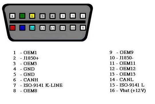 Op20.jpg [ 45.57 KiB | Viewed 4056 times ]
_________________
Subaru Outback BR9 EDM 2010 EJ253 CVT... Subaru Impreza GG2 JDM 2001 EJ152 AT...
Some Hitachi ROM's modifications...
|
|
| Top |
|
|
|
aaa
|
Post subject: Re: SH Boot Mode How-to Posted: Tue May 18, 2021 5:39 pm |
|
|
| Newbie |
Joined: Thu Apr 22, 2021 1:57 am
Posts: 28
|
|
Thanks. It didn't work. I guess I have to wait to get the other parts. It might need Ignition Control, but that is 3.3V.
| Attachments: |

IMG_20210518_103750~2.jpg [ 986.71 KiB | Viewed 4056 times ]
|
|
|
| Top |
|
|
|
SergArb
|
Post subject: Re: SH Boot Mode How-to Posted: Wed May 19, 2021 3:25 am |
|
|
| Experienced |
|
Joined: Sun Aug 18, 2019 12:10 pm
Posts: 278
Location: Russia, Ulan-Ude (Near Lake Baikal)
|
|
OP from China... May have bad soldering on obd connector, try to disassemble it and check. After re soldering, usually, works fine.
Then put ecu back in car, if this don't help... Disconnect CAN lines. Just pull out this pins, or cut wires. And connect to OP.
_________________
Subaru Outback BR9 EDM 2010 EJ253 CVT... Subaru Impreza GG2 JDM 2001 EJ152 AT...
Some Hitachi ROM's modifications...
|
|
| Top |
|
|
|
SergArb
|
Post subject: Re: SH Boot Mode How-to Posted: Wed May 19, 2021 4:59 am |
|
|
| Experienced |
|
Joined: Sun Aug 18, 2019 12:10 pm
Posts: 278
Location: Russia, Ulan-Ude (Near Lake Baikal)
|
|
Looked at you photo, seems you choose wrong pins for CAN lines. Make a photo in front of OP pins.
_________________
Subaru Outback BR9 EDM 2010 EJ253 CVT... Subaru Impreza GG2 JDM 2001 EJ152 AT...
Some Hitachi ROM's modifications...
|
|
| Top |
|
|
|
aaa
|
Post subject: Re: SH Boot Mode How-to Posted: Wed May 19, 2021 6:36 pm |
|
|
| Newbie |
Joined: Thu Apr 22, 2021 1:57 am
Posts: 28
|
That was it. It connected. Rookie mistake. Thank you Still had an error in test write. May be cheap OP will look into that.. I will try to resolder the OBD port leads. I got it from here.. Maybe there is a better one without paying more than $100? I should just order a different one of this is the problem. https://www.amazon.com/dp/B07Y141X7TeBay has another for $180: https://www.ebay.com/itm/Tactrix-Openpo ... 3941855082Thanks again!
| Attachments: |

IMG_20210519_114016~2.jpg [ 403.51 KiB | Viewed 4025 times ]
|

IMG_20210519_114032~2.jpg [ 422.79 KiB | Viewed 4025 times ]
|
|
|
| Top |
|
|
|
SergArb
|
Post subject: Re: SH Boot Mode How-to Posted: Thu May 20, 2021 1:13 am |
|
|
| Experienced |
|
Joined: Sun Aug 18, 2019 12:10 pm
Posts: 278
Location: Russia, Ulan-Ude (Near Lake Baikal)
|
Look on the L3, it lift in the air? Check all elements, quality is really bad... Attachment:
 IMG_20210519_114032~2.jpg [ 548.75 KiB | Viewed 4021 times ]
_________________
Subaru Outback BR9 EDM 2010 EJ253 CVT... Subaru Impreza GG2 JDM 2001 EJ152 AT...
Some Hitachi ROM's modifications...
|
|
| Top |
|
|
|
aaa
|
Post subject: Re: SH Boot Mode How-to Posted: Thu May 20, 2021 1:24 am |
|
|
| Newbie |
Joined: Thu Apr 22, 2021 1:57 am
Posts: 28
|
Yes, I was going to mention that. Thanks. I can check the connections, but I need to get a better DMM multimeter to be able to check. I found this YouTube also. So I'll check if the 5V power chip is working. If not I have some 12v to 5v chips. https://youtu.be/N4XJSuh10XsEdit: got the led working on 5v like in the video but still has error at 80%... Nope still fails random percentage, but have new error message now: "failed to validate flash buffer!.. failure in flash block"
|
|
| Top |
|
|
|
aaa
|
Post subject: Re: SH Boot Mode How-to Posted: Sun May 23, 2021 3:18 am |
|
|
| Newbie |
Joined: Thu Apr 22, 2021 1:57 am
Posts: 28
|
|
I got the 555 timer and it sounds right when hooked up to a speaker (before the last resistor on the watchdog). Still won't flash bootloader, so must be my cheap VAGCOM.. waiting for DLP232M.
I also ordered a normal Tactrix, used $150. Just hooked up and after Windows searching and installing driver, test write was fine. Ecuflash hung for a while after finished, but came back. Real write had error though, which seems odd because it shouldn't have written anything in test mode.. so I restarted Ecuflash, reset power on rig and waited a couple minutes, but still having J2534 error..?? Made no other changes between test write and write.
"
[19:52:24.107] waiting for bootloader (may be installing drivers)... press any key to abort
[19:52:27.137] connecting to bootloader on \
[19:52:27.184] bootloader found.
[19:52:28.207] ---erasing---
[19:52:28.348] ---writing---
[19:52:28.379] writing 1k
...
[19:52:30.937] writing 73k
[19:52:30.984] writing 74k
[19:52:30.984] flash complete!!!
[19:53:22.718] J2534 error [no devices available]
[19:53:22.718] unable to connect to vehicle interface.
[19:53:22.718] interface close
[19:53:49.858] J2534 API Version: 04.04"
It looks like this was a non-test write. and it usually shows a GUI progress bar for percentage done, but I'm pretty darn sure I hit test write as I'm trying to do everything as perfect as possible. It looks like I might have bricked my second ecu though as it won't even read now. Probably happened when it hung at the end, but I didn't interrupt it, the log file shows it come back after 52 seconds.
Last edited by aaa on Sun May 23, 2021 3:35 am, edited 3 times in total.
|
|
| Top |
|
|
|
Suba Imp
|
Post subject: Re: SH Boot Mode How-to Posted: Sun May 23, 2021 3:22 am |
|
|
| RomRaider Donator |
 |
Joined: Fri Sep 18, 2020 1:06 am
Posts: 100
|
I feel for you aaa. This should be a lesson learned, that when it comes to your car, being cheap is not always the way to go, especially with the bits that make the car run. Especially if it's a daily driver. Anyhow, gotta show off my Boot Board. Tested and verified multiple times. Attachment:
 20210522_221813.jpg [ 755.16 KiB | Viewed 3992 times ]
Attachment:
 20210522_222231.jpg [ 446.42 KiB | Viewed 3992 times ]
This cost me a total of 20 US Dollars give or take a few. I did have the green board already from a kit I bought to program IC402. Definitely a learning experience. The chip you want is ft232rl . I used this board https://www.amazon.com/TinySine-Micro-B ... B00N4MCS1A . There are others that are cheaper but I know this one works. Guess I got blessed.
_________________
God First
2010 Subaru Impreza 2.5i NA MT Premium Second
-Hybrid Intake
-0.002 milled heads
-Ported and polished heads.
-Invidia N1 Cat back
-Grounding Kit
|
|
| Top |
|
|
|
Suba Imp
|
Post subject: Re: SH Boot Mode How-to Posted: Sun May 23, 2021 3:34 am |
|
|
| RomRaider Donator |
|
Joined: Fri Sep 18, 2020 1:06 am
Posts: 100
|
|
I know it's a pain but ohm out the wires coming from your rig to the test holes on the ecu, some of your solder joints didn't look so hot, or maybe to hot and burned up the trace.
_________________
God First
2010 Subaru Impreza 2.5i NA MT Premium Second
-Hybrid Intake
-0.002 milled heads
-Ported and polished heads.
-Invidia N1 Cat back
-Grounding Kit
|
|
| Top |
|
|
|
aaa
|
Post subject: Re: SH Boot Mode How-to Posted: Sun May 23, 2021 3:43 am |
|
|
| Newbie |
Joined: Thu Apr 22, 2021 1:57 am
Posts: 28
|
Thanks Suba Imp. Yeah, it was a gamble on the $36 version versus the $170 version, but I didn't think it would be this much of a saga to recover. Luckily not my daily driver, but use it sometimes for work so costing me a bit there. If I get a solution though, well worth it because all of Subaru's new cats are garbage and also cost $1-2k. Fortunately my state dropped testing. And yes my solder tip isn't the finest for this small of work. But I did test for any leakage between, and connectivity. I'll test again. Anyway, thanks for the FTDI board link. What is the silver cylinder interface at the top, an audio jack? And do you connect it with Arduino? What was the learning experience part, to program it? Please share. Thanks! EDIT: Which kit did the green board come from? And I've almost taken the FTDI chip from my VAGCOM and built the shbootmode.pdf schematic, but I need to order a kit with inductors. The small kits I linked above didn't have any. I'm thinking about ordering the XXXL kit so I shouldn't need to order any generic passive again. It's about $150, I'll link, but has about every passive component one could want. I was pretty sure the real Tactrix was going to solve this though. (Part of me thinks the NA PZEV has something to do with my troubles because the hex file is so different from the base). Oh, also, what did you use for the 'L1 ferrite' in the shbootmode.pdf? Literally just a small coil of wire? Would breadboard connector wire work or do I need enameled coil wire? Would a 'basic' inductor work? This is what I am usually happier investing money in, versus an adapter I might use only once or twice. That was the thinking anyway. I'll list a couple more less expensive kits I haven't ruled out though. Chime in if you have an opinion on if the XXXL is overkill though. I know it depends on my plans for usage, but I was surprised the basic kit and Arduino kit didn't have a single inductor. So I'm thinking maybe down the road I'll find the medium kits didn't have something I also consider essential. A) https://www.amazon.com/Electronic-Assor ... B08LZNX7VC $159 B) https://www.amazon.com/Electronic-Assor ... B08MDQ973T $79 C) https://www.amazon.com/Electronic-Compo ... B073TKQNL3 $49 A) looks like it has some clocks and more ICs, but I think I can do all that with Arduino. I could use the Mosfets/Transistors for a very low power draw low voltage battery cutoff on youtube, needs a PNP and NPN. And also the power transistors/regulators, as those seem pretty useful, though could be found on old power tools, so B) might be okay. And also C) has some transistors that are PNP, NPN, but doesn't say Mosfet so might not be low-power draw, and also maybe some power transistors (I need to look those part numbers up). Btw, I hope I'm not highjacking this thread. My initial hope was to write up a 'cheaper' way, maybe with an Arduino 125hz oscillator, but it's gone quite far from that target.
Last edited by aaa on Sun May 23, 2021 4:31 am, edited 1 time in total.
|
|
| Top |
|
|
Who is online |
Users browsing this forum: No registered users and 2 guests |
|
You cannot post new topics in this forum
You cannot reply to topics in this forum
You cannot edit your posts in this forum
You cannot delete your posts in this forum
You cannot post attachments in this forum
|
|


