|
RomRaider
Documentation
Community
Developers
|
| Author |
Message |
|
subarutech77
|
Post subject: SH Boot Mode How-to  Posted: Posted: Sun Jul 03, 2011 1:56 am |
|
 |
| RomRaider Donator |
Joined: Fri Jul 17, 2009 2:47 am
Posts: 77
|
A few months ago I managed to brick the ECU of my 05 FXT, the recovery service from Tactrix was unavailable at the time, and as I understand it now is no longer available. Here’s how I went about building the circuit(s) necessary to use EcuFlash to recover the 7058 in my ECU. BIG THANKS to dschultz and Sasha_A80, without their help, I’d probably still be staring at the ECU and computer screen trying to figure out what I wasn’t doing correctly. Another great write-up http://forums.nasioc.com/forums/showthread.php?t=2200443- Thanks to NSFW for pointing me to this First you’ll need the schematic from Tactrix: Attachment:
 shbootmode.pdf [32.54 KiB]
Downloaded 4236 times
shbootmode.pdf [32.54 KiB]
Downloaded 4236 times
For the timer circuit you will need: 555 timer 2 1K ohm resistors 1 47.5K ohm resistors (I couldn’t find one of these at the local RadioShack, I ended up using 1 46.5K ohm and 2 500K ohm resistors to get to the correct resistance) 1 100nF capacitor (also a .1uF works- same value, again all I could find at RS) A circuit breadboard, I used a solderless one, mostly for ease of construction and could easily fix mistakes made during troubleshooting All of these components can be found at RadioShack or your favorite electronics store, for under $15USD Timer circuit completed on board: Attachment:
 timer.JPG [ 138 KiB | Viewed 43198 times ]
The light blue wire is the output of the timer, should be clocking at 125Hz. Connected to P407 on the ECU The red wire that is exiting the top of the picture is connected to P405 on the ECU, and the other red wire is 5VDC supply(explained later in this post) The black wire exiting the bottom of the picture is connected to P413 on the ECU, the other is the ground for the 5V power circuit. On the 555 timer package from Radio Shack it has the pinouts for the timer, here’s another great site about the 555 timer and its possible uses including a pinout for the timer, also there’s a dot molded on the timer case that signifies pin #1 http://www.doctronics.co.uk/555.htm#pinsFor the USB->Serial device, there are many options. I used a ebay vag-com cable I picked up for about $20. You can also get a DLP232 chip, I have one from Digi-key, I think it was about $25. On the thread referenced above he shows how to hook that up. I’m working on adding the one to the breadboard I have to make it one neat package instead of what I have here. After opening the vag-com cable and using the datasheet for the FTDI chip inside the vag-com cable, page 6 shows the pin diagram: Attachment:
DS_FT232BL_BQ.pdf [1.13 MiB]
Downloaded 2696 times
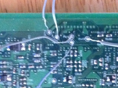
Make the connections necessary to the ECU PCB. Attachment:
 ECU.JPG [ 152.54 KiB | Viewed 43198 times ]
P409 is connected to pin 25(TX) of the vag-com cable, and P411 is connected to pin 24(RX) of the vag-com cable, just like in the Tactrix schematic, I did not need to invert the vag-com signal. In order for the vag-com cable to work properly, I had to pull pins 24-25 off of the vag-com’s circuit board, but kept them attached to the chip. I also had to power the vag-com cable through the OBD2 connector. I picked up a few male OBD2 connectors at the local PicknPull and powered it with the same 12V that powered up the ECU. Attachment:
 vag-com.JPG [ 118.93 KiB | Viewed 43198 times ]
Also you’ll need to power up your ECU, most ECU’s have different pins for power and ground. Reference a service manual to be sure you are using the correct pins, I powered up the power supply pins and backup power and ignition switch pin in my ECU, and connected the power supply grounds. Good to go, right? After firing up EcuFlash with the alternate flash mode option checked in the options menu and the stock ROM for my ECU loaded up(Tactrix did that, I felt it was good practice), It did not work the first few dozen times, I ended up supplying a 5V power source to P405 and the timer circuit separate from the 12V power circuit. EUREKA! It worked. Attachment:
 Set-up.JPG [ 109.66 KiB | Viewed 43198 times ]
Sample of successful SH Boot reprogram: Attachment:
shboot success.txt [373.86 KiB]
Downloaded 2162 times
Redundant? Most probably, but hey, it worked  The 5V source is from a BasicStamp Homework Board that comes in a “What’s a microcontroller” kit from RadioShack, you can also get at the Parrallax website. I highly recommend this kit for people with very little electronics know-how (like myself), it’s really opened my eyes on how a microcontroller works and basic programming syntax. However, any 12V and 5V source should work. Hope this helps a few people, link to troubleshooting thread I started when I had everything together but was running in circles: http://www.romraider.com/forum/viewtopic.php?f=7&t=7136Also, very important!!! Be sure that the ROM/HEX file you are using is good. I had successfully SH Booted my ECU with the stock ROM and went out to reflash it with my latest modified ROM and it bricked the ECU again. I ended up having a corrupt ROM file, I used SH Boot Mode about 4 times backtracking through my revisions until I found one that was good. That would have been very expensive/frustrating if I had to send it to Tactrix every time that happened. This should probably be said too, DISCLAIMER: It is possible to permanently damage your ECU if done incorrectly, I make no guarantees this will work for your situation.
Last edited by subarutech77 on Sun Jul 03, 2011 4:31 am, edited 2 times in total.
|
|
| Top |
|
 |
|
Mart
|
Post subject: Re: SH Boot Mode How-to Posted: Sun Jul 03, 2011 2:05 am |
|
|
| Experienced |
Joined: Sun Jun 01, 2008 2:14 am
Posts: 125
Location: Quebec
|
Nice how to  Mart subarutech77 wrote: A few months ago I managed to brick the ECU of my 05 FXT, the recovery service from Tactrix was unavailable at the time, and as I understand it now is no longer available. Here’s how I went about building the circuit(s) necessary to use EcuFlash to recover the 7058 in my ECU. BIG THANKS to dschultz and Sasha_A80, without their help, I’d probably still be staring at the ECU and computer screen trying to figure out what I wasn’t doing correctly. Another great write-up http://forums.nasioc.com/forums/showthread.php?t=2200443- Thanks to NSFW for pointing me to this First you’ll need the schematic from Tactrix: Attachment: shbootmode.pdf For the timer circuit you will need: 555 timer 2 1K ohm resistors 1 47.5K ohm resistors (I couldn’t find one of these at the local RadioShack, I ended up using 1 46.5K ohm and 2 500K ohm resistors to get to the correct resistance) 1 100nF capacitor (also a .1uF works- same value, again all I could find at RS) A circuit breadboard, I used a solderless one, mostly for ease of construction and could easily fix mistakes made during troubleshooting All of these components can be found at RadioShack or your favorite electronics store, for under $15USD Timer circuit completed on board: Attachment: timer.JPG The light blue wire is the output of the timer, should be clocking at 125Hz. Connected to P407 on the ECU The red wire that is exiting the top of the picture is connected to P405 on the ECU, and the other red wire is 5VDC supply(explained later in this post) The black wire exiting the bottom of the picture is connected to P413 on the ECU, the other is the ground for the 5V power circuit. On the 555 timer package from Radio Shack it has the pinouts for the timer, here’s another great site about the 555 timer and its possible uses including a pinout for the timer, also there’s a dot molded on the timer case that signifies pin #1 http://www.doctronics.co.uk/555.htm#pinsFor the USB->Serial device, there are many options. I used a ebay vag-com cable I picked up for about $20. You can also get a DLP232 chip, I have one from Digi-key, I think it was about $25. On the thread referenced above he shows how to hook that up. I’m working on adding the one to the breadboard I have to make it one neat package instead of what I have here. After opening the vag-com cable and using the datasheet for the FTDI chip inside the vag-com cable, page 6 shows the pin diagram: Attachment: DS_FT232BL_BQ.pdf Make the connections necessary to the ECU PCB. Attachment: ECU.JPG P409 is connected to pin 25(TX) of the vag-com cable, and P411 is connected to pin 24(RX) of the vag-com cable, just like in the Tactrix schematic, I did not need to invert the vag-com signal. In order for the vag-com cable to work properly, I had to pull pins 24-25 off of the vag-com’s circuit board, but kept them attached to the chip. I also had to power the vag-com cable through the OBD2 connector. I picked up a few male OBD2 connectors at the local PicknPull and powered it with the same 12V that powered up the ECU. Attachment: vag-com.JPG Also you’ll need to power up your ECU, most ECU’s have different pins for power and ground. Reference a service manual to be sure you are using the correct pins, I powered up the power supply pins and backup power and ignition switch pin in my ECU, and connected the power supply grounds. Good to go, right? After firing up EcuFlash with the alternate flash mode option checked in the options menu and the stock ROM for my ECU loaded up(Tactrix did that, I felt it was good practice), It did not work the first few dozen times, I ended up supplying a 5V power source to P405 and the timer circuit separate from the 12V power circuit. EUREKA! It worked. Attachment: Set-up.JPG Sample of successful SH Boot reprogram: Attachment: shboot success.txt Redundant? Most probably, but hey, it worked The 5V source is from a BasicStamp Homework Board that comes in a “What’s a microcontroller” kit from RadioShack, you can also get at the Parrallax website. I highly recommend this kit for people with very little electronics know-how (like myself), it’s really opened my eyes on how a microcontroller works and basic programming syntax. However, any 12V and 5V source should work. Hope this helps a few people, link to troubleshooting thread I started when I had everything together but was running in circles: http://www.romraider.com/forum/viewtopic.php?f=7&t=7136Also, very important!!! Be sure that the ROM/HEX file you are using is good. I had successfully SH Booted my ECU with the stock ROM and went out to reflash it with my latest modified ROM and it bricked the ECU again. I ended up having a corrupt ROM file, I used SH Boot Mode about 4 times backtracking through my revisions until I found one that was good. That would have been very expensive/frustrating if I had to send it to Tactrix every time that happened.
|
|
| Top |
|
|
|
MFB
|
Post subject: Re: SH Boot Mode How-to Posted: Sun Jul 03, 2011 3:16 am |
|
|
| RomRaider Donator |
 |
Joined: Mon Dec 15, 2008 7:12 am
Posts: 672
Location: The Philippines
|
Hope romraider and ecuflash can have the ability to know if the image is fit or not. Ive had my own share of bad flashing but when this happen, Im able to just reflash again. Just dont turn off the ignition so interface is still open. However Im sure there are other reasons for a bad flash. Ex. hardware, virtual environment, incompatible driver, etc. Nice how to thread! Thanks for sharing
|
|
| Top |
|
|
|
Sasha_A80
|
Post subject: Re: SH Boot Mode How-to Posted: Sun Jul 03, 2011 2:03 pm |
|
|
| Senior Member |
Joined: Mon Jan 19, 2009 6:31 pm
Posts: 1615
Location: Moscow, Russia
|
|
ecuFlash knows whether ROM image is corrupt or not provided RomRaider did not clear ROM checksum before.
|
|
| Top |
|
|
|
B-BGTLimited
|
Post subject: Re: SH Boot Mode How-to Posted: Fri Jul 29, 2011 3:25 pm |
|
|
| RomRaider Donator |
Joined: Thu May 20, 2010 11:59 am
Posts: 62
|
|
This is nice info to have but Tactrix will still do this recovery service. They just did one for me last week.
_________________
I drive a Pink Beretta...
|
|
| Top |
|
|
|
Jochen_145
|
Post subject: Re: SH Boot Mode How-to Posted: Wed Aug 10, 2011 8:50 am |
|
|
| Experienced |
 |
Joined: Wed Nov 10, 2010 11:56 am
Posts: 418
|
really nice discription I hope this can help on a Diesel ECU as well, but I am really confident about this.. Maybe it is possble for me, to get a bricked up diesel ECU. To re-animate it, I will try to use the SHbootmode or the renesas Flash developer toolkit.. (btw.: does anyone knows, if this tool kit is a "over-all" free version, or is it just a try-kit for a few month?) Just a few more questions: - at the moment, there is no OS flasher availble, so is it a way to flash "everytime" with this SBootmode instate of OBD-flashing ? (if yes, i will wire all relevant pins to a additional plug and implementate the timer in a "boot-Mode-interface") - renesas flasher tool kit needs also the same hardware (incl. watch-dog timer) liek the ECUflash software ? - flashing in SHboot-mode needs a komplete dump ? (a few diesel dumps are around, here the first 16kb are missing) - IMMO part is inside the ROM, not the flash ? So no need to take care of IMMO ishes, when reanimation a ECU via SHbootmode, if the ECU remains the to car ? OT: If I can re-animate a bricked Diesel ECU, i like to have it as eveluation ECU for the Diesel. Is there a simple way to read out my ROM from my frist ECU and write it to the eveluation ECU , in short: how to clone a diesel ECU ? BR Jochen
_________________
performence based on engineering..
Last edited by Jochen_145 on Wed Aug 10, 2011 10:54 am, edited 1 time in total.
|
|
| Top |
|
|
|
Sasha_A80
|
Post subject: Re: SH Boot Mode How-to Posted: Wed Aug 10, 2011 10:12 am |
|
|
| Senior Member |
Joined: Mon Jan 19, 2009 6:31 pm
Posts: 1615
Location: Moscow, Russia
|
1. FDT is a full featured unsupported version. The limitation is that it is artificially slows down writing to a flash memory ( as like it is done at 9600 bps, about 20min/1 MB flash). ROM verification\reading is done at full (57600) speed. 2. Tried to flash 7055F based ecu about 300 times (100 is promised by datasheet, 10000 evaluated later). 3. Watchdog is a must for Denso ecu. 4. You are to have a complete dump. The whole ecu content is erased after flash mode is entered. 5. You are free to create the initial bootloader on your own and to make a complete ROM image. 6. Immo lives outside the SH chip. Find something like 93с66 chip probably connected to SCI3 port of SH7059. 7. Ask for those who can overcome disabled AUD interface in order to get the ROM or reinvent a bootloader. Attachment:
 AG572_PROG.JPG [ 131.22 KiB | Viewed 42958 times ]
Added: FDT software ver.4.07 does not artificially slow writing down.
Last edited by Sasha_A80 on Sun Sep 04, 2011 7:18 am, edited 1 time in total.
|
|
| Top |
|
|
|
Jochen_145
|
Post subject: Re: SH Boot Mode How-to Posted: Wed Aug 10, 2011 11:07 am |
|
|
| Experienced |
|
Joined: Wed Nov 10, 2010 11:56 am
Posts: 418
|
Sasha_A80 wrote: 1. FDT is a full featured unsupported version. The limitation is that it is artificially slows down writing to a flash memory ( as like it is done at 9600 bps, about 20min/1 MB flash). ROM verification\reading is done at full (57600) speed. Great: If my coffee-mashine on, I got no problem with the flashing time I didn´t reconized, that I also can download with the FDT, but it sounds very good Overall: with some ironing work on the ECU, the FDT is a complete flash-tool for the renesas ecus So no more wating for other flasher.. Quote: 4. You are to have a complete dump. The whole ecu content is erased after flash mode is entered. ok.. but I can get this by a read out with the FDT (?!) Quote: 5. You are free to create the initial bootloader on your own and to make a complete ROM image. mhh.. I am not aprogrammier, I am applicatieur, so froo this I need "running systems" that is my probelm so fare  Quote: 6. Immo lives outside the SH chip. Find something like 93с66 chip probably connected to SCI3 port of SH7059. Is there a "easy" chance to read and wirte this chip ? So I can read my IMMO and wirte the data to the secound ECU Quote: 7. Ask for those who can overcome disabled AUD interface in order to get the ROM or reinvent a bootloader. That´s what I mean.. Is this a solution , what allready exsists and is buyable ? BR Jochen
_________________
performence based on engineering..
|
|
| Top |
|
|
|
Sasha_A80
|
Post subject: Re: SH Boot Mode How-to Posted: Wed Aug 10, 2011 11:29 am |
|
|
| Senior Member |
Joined: Mon Jan 19, 2009 6:31 pm
Posts: 1615
Location: Moscow, Russia
|
|
You may read the flash by means of FDT JUST AFTER you have wrote this flash image. After FDT is disconnected and reconnected again ALL flash content will be erased.
It is not a feature of FDT. The chip microcode does this.
SPI\I2C flash programmer is a standard equipment for those immo chips. From the other hand you are free to write a program for SH to make a copy of the immo chip ( in the same manner as a bootloader kernel is created\ loaded into to RAM currently ).
Have you ever seen door lock unlockers retailed? This is a professional eqiupment...
I think it will be much simplier to order ROM image upload procedure to be done by a third party if you unable to do it yourself.
|
|
| Top |
|
|
|
franko
|
Post subject: Re: SH Boot Mode How-to Posted: Sun Sep 04, 2011 6:25 am |
|
|
| Newbie |
Joined: Tue Aug 25, 2009 2:29 am
Posts: 26
|
|
Hooray! Someone found my thread helpful!
|
|
| Top |
|
|
|
2bfi
|
Post subject: Re: SH Boot Mode How-to Posted: Fri Sep 16, 2011 11:18 pm |
|
|
| RomRaider Donator |
Joined: Fri Dec 25, 2009 12:46 pm
Posts: 93
|
|
Thanks for the great write up. I've assembled my own circuit as an insurance against a bricked ecu.
I got a question about powering up the ecu. Can I leave it connected to the car and switch the key to ON? It seems much quicker than tracing the pins and soldering wires to them.
|
|
| Top |
|
|
|
subarutech77
|
Post subject: Re: SH Boot Mode How-to Posted: Fri Sep 16, 2011 11:36 pm |
|
|
| RomRaider Donator |
Joined: Fri Jul 17, 2009 2:47 am
Posts: 77
|
2bfi wrote: Thanks for the great write up. I've assembled my own circuit as an insurance against a bricked ecu.
I got a question about powering up the ecu. Can I leave it connected to the car and switch the key to ON? It seems much quicker than tracing the pins and soldering wires to them. No this method only works with the wires soldered to the board, once that's in place I suppose you could plug it back in the car and have it work.
|
|
| Top |
|
|
|
2bfi
|
Post subject: Re: SH Boot Mode How-to Posted: Sat Sep 17, 2011 12:31 am |
|
|
| RomRaider Donator |
Joined: Fri Dec 25, 2009 12:46 pm
Posts: 93
|
subarutech77 wrote: 2bfi wrote: Thanks for the great write up. I've assembled my own circuit as an insurance against a bricked ecu.
I got a question about powering up the ecu. Can I leave it connected to the car and switch the key to ON? It seems much quicker than tracing the pins and soldering wires to them. No this method only works with the wires soldered to the board, once that's in place I suppose you could plug it back in the car and have it work. Sorry, I wasn't too clear. I meant soldering the wires from the circuit board to the ecu then powering up the ecu by plugging it into the car. That way, I don't have to trace the power and ground wires on the ecu. I think you already answer that in your last sentence. Thanks.
|
|
| Top |
|
|
|
Sasha_A80
|
Post subject: Re: SH Boot Mode How-to Posted: Sat Sep 17, 2011 2:35 am |
|
|
| Senior Member |
Joined: Mon Jan 19, 2009 6:31 pm
Posts: 1615
Location: Moscow, Russia
|
|
I use to do this way.
You are to solder just Gnd/Watchdog/Rx/Tx wires for programming and connect the programmer and the ecu back to the car wiring ( in that order ).
Do not forget to use protective resistors about 5kOm/1kOm/5kOm for Watchdog/Rx/Tx.
Added:
- and make proper wiring for FWE and MD1 circuitry in order to enter bootmode.
|
|
| Top |
|
|
|
2bfi
|
Post subject: Re: SH Boot Mode How-to Posted: Sat Sep 17, 2011 5:01 am |
|
|
| RomRaider Donator |
Joined: Fri Dec 25, 2009 12:46 pm
Posts: 93
|
Sasha_A80 wrote: I use to do this way.
You are to solder just Gnd/Watchdog/Rx/Tx wires for programming and connect the programmer and the ecu back to the car wiring ( in that order ).
Do not forget to use protective resistors about 5kOm/1kOm/5kOm for Watchdog/Rx/Tx.
Added:
- and make proper wiring for FWE and MD1 circuitry in order to enter bootmode. The schematic from tactrix doesn't have protective resistors on the Tx & Rx lines, and only a 1k ohm resistor or the Watchdog line. Is it because we are powering directly from the vehicle? Or is it an added safety measure?
|
|
| Top |
|
|
Who is online |
Users browsing this forum: No registered users and 1 guest |
|
You cannot post new topics in this forum
You cannot reply to topics in this forum
You cannot edit your posts in this forum
You cannot delete your posts in this forum
You cannot post attachments in this forum
|
|


