How to read EEPROMS on 05- 09 Subaru Ecu (Possibly Many more)- Method is without removing the EEPROM from the board. There is an alternate method by just physically moving the eeproms to the donor units but that's pretty straight forward. This is the digital way and gives you a backup file, and no solder skills needed.
Items Needed: Laptop or Desktop PC running windows 7 or newer. **64/32 bit irrelevant
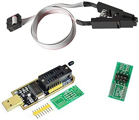
CH341A – Chinese EEPROM Programmer (Black Edition) + Clip on Adapter Shown Below
Drivers for the CH341A - I used google and got this one - CH341PAR.EXE - self installing archive with multi-protocol interface driver (this one is for the programmer mode)
Link:
https://www.onetransistor.eu/2017/08/ch ... matic.htmlAttachment:
File comment: CH341A – Chinese EEPROM Programmer (Black Edition)
 1.jpg [ 79.01 KiB | Viewed 8484 times ]
Cable / Wire to connect between programmer and clip. Preferably different colors
and male to male ends. ( Pictured Below )
Attachment:
File comment: Cable / Wire to connect
 2.jpg [ 140.49 KiB | Viewed 8484 times ]
Your choice of Hex Editor programs. Many free Hex editors on the web. Use google.
Lastly, a programmer capable of reading the EEPROMS.
I used NEOProgrammer. It's free from the website below. Link may die eventually.
Link:
https://khandishnetwork.com/dl/neoprogr ... 2-06-2021/Attachment:
File comment: NeoProgrammer Software 2021 V2.2.0.8 – 22/06/2021
 NeoProgrammer V2.2.0.8.rar [7.07 MiB]
Downloaded 226 times
NeoProgrammer V2.2.0.8.rar [7.07 MiB]
Downloaded 226 times
The Setup: 1st off I want to start this off by stating some of the prerequisites and warnings.
You are going to do this at your own risk, I assume no liability for damages that you cause to your ecu, cluster or biu. You are going to continue at your own risk and by doing so you are agreeing that you understand you are 100% liable and can cause irreversible damage to your components.
You should only continue if you are highly comfortable with what you are doing, understand that if you do manage to erase the data without a backup you will need to purchase all new equipment from Subaru and may cost well over 2000$ USD. Do not take this lightly. Trust me.
You will need to remove your ECU and BIU from the car that has working keys. If its 2nd hand or the unit from your car, you need to have a matching BIU / ECU with at least one paired key, I can not help you if you have erased your EEPROM and do not have a backup, or you are trying to program without a working system to get data from.
If you are just changing out the ECU you only need to remove the ECU, or if only changing the BIU you only need to remove the BIU. This will cover both the ECU and BIU for documentation purposes.
Ok, so it's safe to assume, you have a ECU or BIU or maybe both sitting next to you at your desk and you are starting to prepare your tools. 1st lets identify what the ECU EEPROM is and location, as well as the BIU. This is where you will be connecting your test connector to read the stored data.
Think of the EEPROM as a mini SD card with all the secrets saved on it ready to read.
What am I looking for? EEPROMS?
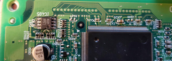
They are 8 pin Micro-wire chips shown below. Have a look!Attachment:
File comment: 8 pin Micro-wire chip
 3.jpg [ 466.62 KiB | Viewed 8484 times ]
ECU EEPROM:
With ECU main connections facing you, the EEPROM is in the upper left corner of the ECU.
EEPROMS on these boards have 8 pins, 4 on either side, and are marked either L56R or 93c56R
These are both Micro-wire EEPROMS. The Ecu uses 5v and the BIU uses 3.3v. Will show in system as 93c56R – Make sure to choose 5V one.
Attachment:
File comment: L56R or 93c56R Micro-wire EEPROM
 4.jpg [ 428.57 KiB | Viewed 8484 times ]
BIU EEPROM:With the connector facing you, you must turn the board over and look at the rear of the board. The EEPROM is located near the top and middle of the BIU board. It is labeled s24c01 and is 3.3v.
Chip will display in reader as 24c16 3.3V
More Banter, And prepping the CH431A to support 5v EEPROMS.Okay,
So you now know where the EEPROMS are located. Guess what there's a 3rd one on your cluster too! But I haven’t pulled my cluster, nor do I really want to. This was a costly lesson I’ve learned, and in the end I’m just trying to save others from the hassle I’ve had with this. As well I’ve also managed to get a virgin ECU file and BIU by purchasing the items new and never flashed. So basically a 2000$ Unmarried ecu file used to clean used Ecu’s. But that's later and may never be shared publicly, as it cost me a fortune to acquire.
****Also I will not discuss how to change or edit the cluster due to the Mileage being saved on the cluster. Google it yourself, but I’m not helping you rollback miles, or anything of that nature. Sorry, not really, I’m the one who's out the 2k for learning this mess so you don't have to screw it up like I did.Back to the fun stuff…Now you have the Tools, The computer programs installed, your ECU or BIU laying next to you,
Now we need to prepare the tool for use on the ECU.
Let's start off by setting up the CH341A black edition to support the ECU EEPROM, and have it be able to put out the 5V to read the chip in the board.
You’ll need a solder Iron for this part, or you can use the jumper on the side and see if it works for you, I went ahead and did the Solder mod for 5v constant to the lower 25xxx section of the reader.
The upper 24xxx section will still support 3.3v so no worries. This is the only stage you need to add any solder to the unit, you will need to heat up one pin to remove it but this is the only stage needing solder / solder iron.
Below are the modifications to have the 25xxx slot support 5v.
You will need to connect the 5v lead from the 5 volt pin in the top right to the top right pin on the 25xx connection. My solder job is horrible, and I just used some scrap wire to make a jumper, you can do better than me, I was just going for it. You can even see the ball of solder that I accidentally dropped on the outside ring, whoops. Oh well.
Attachment:
File comment: 5v lead from the 5 volt pin
 5.jpg [ 377.49 KiB | Viewed 8484 times ]
I also cut the trace to the 25xx on the board to avoid voltage spikes. This probably wasn’t needed. You can do it too, but it's probably a waste of time and can cause issues if you cut the ground that is close to it. But that’s what those “scratched up marks are''
Now to the other side.
Attachment:
File comment: the other side
 6.jpg [ 483.87 KiB | Viewed 8484 times ]
Here on that center black chip – Its the voltage regulator, the middle pin out of the 3 needs to be lifted off of the board. I just took the solder iron and sat it on there for a little bit and used a pick to lift the little foot off of its pad so it won't make contact. This effectively cuts the restriction of 3.3v to the 25xxx connector.
Attachment:
 7.jpg [ 540.53 KiB | Viewed 8484 times ]
Attachment:
 8.jpg [ 109.16 KiB | Viewed 8484 times ]
Attachment:
 9.jpg [ 570.61 KiB | Viewed 8484 times ]
Attachment:
 10.jpg [ 293.62 KiB | Viewed 8484 times ]
Above shows the programmer hooked up on the 24xxx slot for the BIU. The jumper stays on #1 and #2 for all the flashes I’ve done. With the 5v mod you do not need to jumper the 3v and 5v connectors. I do not know if this will work without doing the 5v mod, so you could try to just have a jumper on 3v and 5v and one on #1 and #2 on the programmer and see if you can read the info, I can't answer that one.
Well done!
You’ve finished preparing your programmer to do what its supposed to do. Read and write these little micro-wire chips! Woot Woot.
Time to wire up your wire clamp and start reading / writing. This is of course if you have already
installed the above prerequisite drivers and programs needed to read / write.
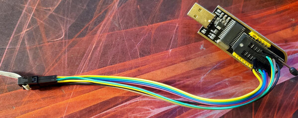
In a nutshell I just used the Male to Male wires and pushed them into the programmer by hand,
and into the connector on the clip probe instead of soldering everything onto a breakout board.
If you like to be fancy, take the supplied breakout board with the kit and wire yourself to it,
me on the other hand, I’m lazy and my shaky hands don’t solder well.
For BIU WIRE Pin Out -
It's literally just number to number for wiring the programmer to the test clip.
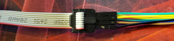
On the EEPROM there is always a little dimple or O in the corner, This is for orientation.
The pin closest to the dimple or 0 is going to be number 1.
So something like this below:
1 - 8
2 - 7
3 - 6
4 - 5
The programmer is numbered the same way. Just remember it has basically 2 slots in it.
The slot closest to the locking lever is the 24xxx slot for 3.3v applications. The hole closest to the lever is number 1.
The slot below it is the 25xxx slot and it follows the same numbering as the chip 1-4 on the left and 8-5 on the right.
So wiring the BIU you literally just go 1 to 1, 2 to 2, and so on until you have all 8 slots connected to your clip matching up. Number one on the clip was marked with a red wire on my clip.
For BIU readout you will be using the 24xxx slot closest to the lever on the programmer.
I used the supplied board to orientate it so I knew what side was 1-4 and 8-5
See below photos: This was pinned out for BIU eeprom reading.
Attachment:
File comment: pinned out for BIU eeprom reading
 11.jpg [ 126.18 KiB | Viewed 8484 times ]
ECU EEPROM Pin out:
1 on Chip to 1 on Programmer
2 on Chip to 6 on Programmer
3 on Chip to 5 on Programmer
4 on Chip to 2 on Programmer
5 on Chip to 4 on Programmer
6 UNhooked
7 UNhooked
8 on Chip to 8 on Programmer
Done. You now have successfully wired up your CH341A to read the ECU eeprom.
Now it's time to use the Neo-programmer to read the ECU or BIU.
The tool is super simple.Open Neo-Programmer and make sure you have the chip connected, and the programmer is plugged into a working USB port. I had my speakers on so I could hear when the disconnect sound played from windows, this told me I had a good connection. To verify if you are connected hit the DETECT button on Neo-programmer. If you get options to choose a chip type you are connected to, if you get a blank box or error message in the logs you are not connected right. Keep trying and hitting detect as you position the clip. I had to hold my clip down while reading / writing to make sure it stayed on, it's a pain, and you’ll learn the best way to do it with trial and error.
Once you have a solid connection and you choose your chip ( this was broken down before )
Newer versions of Neo Programmer may ask for you to choose either 0,1,2 etc. due to multiple options. For the ECU it's under 0.
93c56r_16Bits 5v is the one for ECU / 24c16_8bits 3.3V is the BIU.
Okay, Time to hit the read button and see what happens!
Click the read button located at the top of Neo Programmer. If you get something other than all 0 or F you got it! The top 3 lines should contain Key Data, the next 3 are your VIN repeated 3x. And the last 6 or so lines are a checksum for the ecu and other data that I don’t have knowledge of. This is more so helping you save the entire file so you can clone it over to a donor ecu or store it in-case you have issues with the units.
Below is Neo-Programmer, I’m not going to go into a ton of data on how to use it, its really simple.
The Detect button is huge! Don't try clicking other stuff until you know you can detect and select the appropriate chip type, this way you know your connection is good. Read is the button next to the big floppy disk for “save”. Write is next to read.
Steps – Connect clip to the eeprom. Click detect and choose the appropriate chip you are working with.
Once selected click read and make sure it populates the data. SAVE IT, SAVE IT, SAVE IT.
If you delete this data, corrupt it etc., you will be buying a new ecu and new BIU from Subaru as I have no way to help you recover the key data or security id data. Once you have a good read and saved file, you can now move to the donor ecu follow the first 3 steps and read it, once you know it's readable, detected and working, use the folder icon to open your saved .hex or .bin file you created from your working ecu and then write it to the donor ecu / biu.
This should effectively move your immobilizer over and clone it to the donor, both ecu should be identical and now accept your keys / start the vehicle.
Attachment:
File comment: Programmer
 12.jpg [ 786.41 KiB | Viewed 8484 times ]
Some Additional Take Away Notes: IMPORTANT!!
When Viewing the data using NEOProgrammer, the data is “Backwards” This can be fixed, but you MUST “UN-fix” it prior to writing the data back to the EEPROM. The format is 100% important and if you *(Swap High and Low Bytes)* you must swap them back once you have made changes. This is under Buffer tab on the top panel.
You can verify that the data is skewed by looking at your vin#. If your vin# is reading out correctly you MUST swap the bytes before writing things back, if the vin# is slightly out of order then its in the correct format. The key data will not be valid without this being done!
Below is an explanation of how the Keys and Vin will appear with the Swap high and low bytes being pushed. I have changed the key data to FAKE data as well as the Vin# to a fake vin#.
This is for illustration purposes and is only for reference.
NOTE: Key data is repeated 3x, VIN# is repeated 3x. The other data represents the amount of keys programmed to the ECU.
You will see after the Vin# the ECU ends the code with FFFFF this signify s the run off of code.
The remaining code must NOT BE CHANGED. The bottom section is the HASH / CHECKSUM and is required for verification of the ecu integrity. Changing this will have negative consequences.
In the below Photos:
The vin#: in the reference photo are XX1SGXXXXXXXXXXX ( 16 Digit Vin ) a . for space and repeated 2 more times.
Keys: in the reference photo are 8D88, 7B77 – As well you can see it denotes there are 2 keys by the 00 02 repeated 3x.
This one is where the bytes are swapped to view the vin in the correct format, But is technically invalid:
Attachment:
The attachment FixedStateButWrong.png is no longer available
This one is in the Corrected State but the vin is slightly out of format:
Attachment:
The attachment CorrectState.png is no longer available
In case Photos wont display - Links Die - Here is the Google Drive Link to the Writeup -
UPDATED 9/13/2022
https://drive.google.com/file/d/14tUv86 ... sp=sharing


