|
RomRaider
Documentation
Community
Developers
|
| Author |
Message |
|
Sasha_A80
|
Post subject: Re: SH Boot Mode How-to  Posted: Posted: Sat Apr 27, 2013 6:13 pm |
|
 |
| Senior Member |
Joined: Mon Jan 19, 2009 6:31 pm
Posts: 1615
Location: Moscow, Russia
|
dschultz wrote: comms is via CPU serial 0. This is correct particular for Denso SH7058S based ecu but for others.
|
|
| Top |
|
 |
|
Sasha_A80
|
Post subject: Re: SH Boot Mode How-to Posted: Sat Apr 27, 2013 6:16 pm |
|
|
| Senior Member |
Joined: Mon Jan 19, 2009 6:31 pm
Posts: 1615
Location: Moscow, Russia
|
Jochen_145 wrote: Other question:
what will happen, if I would recover with one of these dumps without the kernel ?
Software, maps, size and checksumm will be o.k. and the kernel is not need for normal work ?
Not exactly. Some hints are needed to run the code. Maps and checks are fine.
|
|
| Top |
|
|
|
Sasha_A80
|
Post subject: Re: SH Boot Mode How-to Posted: Sat Apr 27, 2013 6:23 pm |
|
|
| Senior Member |
Joined: Mon Jan 19, 2009 6:31 pm
Posts: 1615
Location: Moscow, Russia
|
Jochen_145 wrote: As I (tryed) to unterstand, the VBR should be after the checksumm table.
If yes, then this part as well as the the checksumm table, the source code and everything else is reat.
Only the first 16kb with the kernel is missing. It is hard to believe that InterruptVectorTable is read from ecu while the kernel could not be read. I strongly believe the code including IVT is got thru a hack of an official reflash pack.
|
|
| Top |
|
|
|
Jochen_145
|
Post subject: Re: SH Boot Mode How-to Posted: Sat Apr 27, 2013 8:53 pm |
|
|
| Experienced |
 |
Joined: Wed Nov 10, 2010 11:56 am
Posts: 418
|
Sasha_A80 wrote: It is hard to believe that InterruptVectorTable is read from ecu while the kernel could not be read.
I strongly believe the code including IVT is got thru a hack of an official reflash pack. No, it is possible to read the completet dump via OBD, like it is done when you are using AUD-interface. Subaru Diesel Crew flasher works this way, AFAIK. I just saw the resut (complete dump with kernel) but not the way is was readout. The software never reatch me, bevor the project dies. Today I got a OBD readout from a CMD tool: the same, nearly komplete dump, only the kernel (first 16kB) is missing.
_________________
performence based on engineering..
|
|
| Top |
|
|
|
hockey3592
|
Post subject: Re: SH Boot Mode How-to Posted: Fri Nov 15, 2013 1:19 pm |
|
|
| Newbie |
Joined: Sat Nov 12, 2011 1:01 am
Posts: 13
|
|
I was wondering if anyone has any experience with the 08+ ECU's. The caps shown in the pictures aren't on the board in the same way. Greatly appreciate the help!
|
|
| Top |
|
|
|
subarutech77
|
Post subject: Re: SH Boot Mode How-to Posted: Fri Nov 15, 2013 1:27 pm |
|
|
| RomRaider Donator |
Joined: Fri Jul 17, 2009 2:47 am
Posts: 77
|
|
Do you have a picture of the ecm? I dont don't know if id follow this thread, I did it a long time ago and now use a arduino with a timer circuit, much cleaner wiring and such, perhaps .I should update this thread. Have you seen the one on nasioc?
|
|
| Top |
|
|
|
hockey3592
|
Post subject: Re: SH Boot Mode How-to Posted: Fri Nov 15, 2013 4:07 pm |
|
|
| Newbie |
Joined: Sat Nov 12, 2011 1:01 am
Posts: 13
|
subarutech77 wrote: Do you have a picture of the ecm? I dont don't know if id follow this thread, I did it a long time ago and now use a arduino with a timer circuit, much cleaner wiring and such, perhaps .I should update this thread. Have you seen the one on nasioc? I have viewed the one on nasioc and its quite different. I'll get a picture posted up of the ECM. Could you share the Arduino schematic? I have an UNO that I'd love to use over purchasing new hardware.  
|
|
| Top |
|
|
|
subarutech77
|
Post subject: Re: SH Boot Mode How-to Posted: Fri Nov 15, 2013 4:46 pm |
|
|
| RomRaider Donator |
Joined: Fri Jul 17, 2009 2:47 am
Posts: 77
|
|
There they are, in the first pic upper left, right under the big IC402. You'll need p405, p413, p407. Also p411 and p409 are right above the IC402.
If you put the UNO into in tri-state mode by grounding the reset pin, or alternately removing the at328 from its socket, you can use the USB-serial chip on the UNO board, by using the rx and TX pins at the headers. Same concept as buying a USB-serial device. Then I used a proto shield for the timing circuit. Ill try to dig something up tonight, or at the very least take a pic.
I found using the ftd toolkit to work better with this set-up
Then all you need to do is find what pins to power and ground on the ecm wiring harness sockets.
|
|
| Top |
|
|
|
hockey3592
|
Post subject: Re: SH Boot Mode How-to Posted: Fri Nov 15, 2013 5:06 pm |
|
|
| Newbie |
Joined: Sat Nov 12, 2011 1:01 am
Posts: 13
|
|
If you could supply a picture of your setup I would greatly appreciate it. So if you use the reset -> ground method on the UNO you dont have to have any code loaded to it and just use ECUFlash in flash recovery? I'll be plugging the ECM into the car harness to power it up to avoid pin soldering.
|
|
| Top |
|
|
|
Sasha_A80
|
Post subject: Re: SH Boot Mode How-to Posted: Fri Nov 15, 2013 5:12 pm |
|
|
| Senior Member |
Joined: Mon Jan 19, 2009 6:31 pm
Posts: 1615
Location: Moscow, Russia
|
|
CN402
1 PVcc2 SH7058.128
2
3 Watchdog SH7058.164
4 Reset SH7058.58
5
6 FWE SH7058.56
7
8 MD1 SH7058.55
9 TxD1 SH7058.165
10 RxD1 SH7058.166
11 Gnd
12 Gnd
|
|
| Top |
|
|
|
subarutech77
|
Post subject: Re: SH Boot Mode How-to Posted: Fri Nov 15, 2013 5:23 pm |
|
|
| RomRaider Donator |
Joined: Fri Jul 17, 2009 2:47 am
Posts: 77
|
|
Oh cool, that's probably easier to use. Thanks sasha.
@hockey- correct, the arduino chip/code is not used.
|
|
| Top |
|
|
|
subarutech77
|
Post subject: Re: SH Boot Mode How-to Posted: Sat Nov 16, 2013 5:45 am |
|
|
| RomRaider Donator |
Joined: Fri Jul 17, 2009 2:47 am
Posts: 77
|
Hey, here's a fritzing drawing of my protoboard. The wires that run off the board are as follows: green wire goes to p411, yellow to p409, orange to p407, black to p413, red to p405. Attachment:
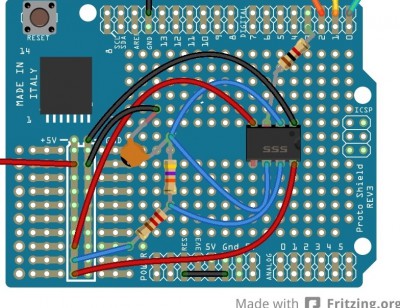 Timer Cicuit on proto board_bb.jpg [ 217.37 KiB | Viewed 10941 times ]
You'll want to try to have a common ground for the arduino and ecm and whatever power source you use. EDIT: the orange wire should be on pin 3 not pin 2, it's the output of the timer off the resistor.
|
|
| Top |
|
|
|
hockey3592
|
Post subject: Re: SH Boot Mode How-to Posted: Sat Nov 16, 2013 2:10 pm |
|
|
| Newbie |
Joined: Sat Nov 12, 2011 1:01 am
Posts: 13
|
|
Much appreciated! I'll hopefully be giving this a go this weekend or early next week.
Sasha, Thanks for the pad locations on the ECM all inline. Those are super easy solder pads to work with.
|
|
| Top |
|
|
|
DmcL
|
Post subject: Re: SH Boot Mode How-to Posted: Mon Apr 21, 2014 9:18 am |
|
|
| Experienced |
 |
Joined: Thu Jul 25, 2013 6:12 pm
Posts: 166
Location: Northern Ireland
|
|
im not the greatest with electrical schematics and things like this, would be worried of not making it right or not right for my A8DH200Y or something.. would someone capable of building one of these and modifying an appropriate USB>serial cable fancy making me the SH boot mode hardware setup? id pay for the parts/your time/shipping to me.
id rather have it and maybe never need to use it than not have it and end up needing it some day as at the minute my WRX is my daily and also the only one of my two cars thats driving.
_________________
MY06 EDM 2.5 WRX
Stage 2 w/LC & FFS, 3" CBE, Stock Dia. SRI, GrimmSpeed 3 Port, More to come...
|
|
| Top |
|
|
|
AudioRuso
|
Post subject: Re: SH Boot Mode How-to Posted: Mon Sep 12, 2016 8:54 pm |
|
|
| Newbie |
 |
Joined: Sun Mar 13, 2016 10:59 pm
Posts: 14
|
I just wanted to add my experience. Being a computer geek and having some components around (and being haunted by having to drive into work from a remote area in the morning) I had to make do with what I had. And what I had was a 5 dollar USB to Serial cable from ebay that proved to be very convenient for the job: Attachment:
 s-l1600.jpg [ 37.32 KiB | Viewed 8526 times ]
I was able to solder normal header pins (the type that come with arduinos or any other standard breadboard) to the appropriate pins on my ECU (from an 08 wrx that was bricked while tuning). I was able to connect to the pins DIRECTLY so no further circuitry for the in circuit programming portion was needed. There's a resistor in the picture below but I'm fairly certain in the end I removed it. Attachment:
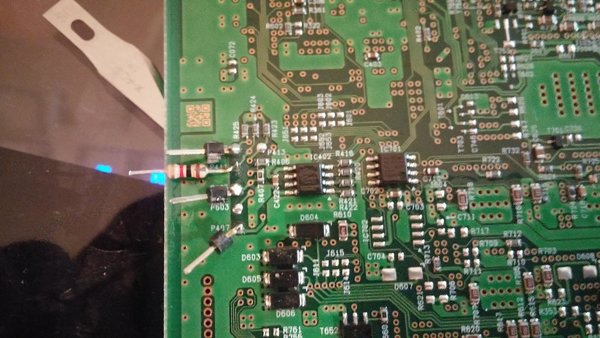 13680396_1153583337995041_9007814499440630983_o.jpg [ 251.42 KiB | Viewed 8526 times ]
The only challenge was the watchdog timer. I didn't want to build a circuit so instead I made another hack and although it was a pain in the ass to get it to work just right, in the end I was able to successfully flash and unbrick the ECU. I used a waveform generator program on the computer which ran a standard square wave into the audio output (but it was offset to 0v to +10v) so it was never going into the negative range. I also used a pulldown resistor to ground on the ECU circuit that was also connected to the ground on the power supply. The power supply was a large 12v brick style power supply (similar to monitor or laptop power supply). Lastly i had to play with the output volume until it was just enough to keep the circuit online while writing the program. I realize this is far from optimum, and far from the right way of doing this, but it's A way that worked for me in a pinch with much less circuitry or manual timers and so on.
|
|
| Top |
|
|
Who is online |
Users browsing this forum: No registered users and 5 guests |
|
You cannot post new topics in this forum
You cannot reply to topics in this forum
You cannot edit your posts in this forum
You cannot delete your posts in this forum
You cannot post attachments in this forum
|
|


